|
CB2 micro
User manual
|
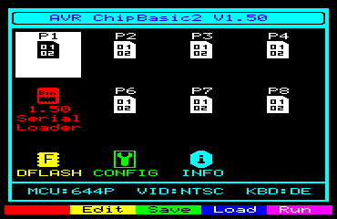
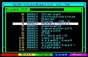
| colour | program type |
| White | BASIC program |
| Green | Program saved as text |
| Yellow | Binary program |
| Cyan | Library |
| Magenta | Video driver, can only be used on program slot 8 |
| Red | Loader program, can neither be edited nor started |
| No function | |
 |
For BASIC programs, the editor is called |
 |
Saves the program on a Dataflash module |
 |
Loads the program from a Dataflash module |
 |
Starts the program |
 |
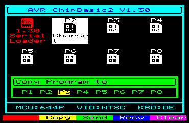
Copies the program to another program slot |
 |
Sends the program via X-modem |
 |
Receives the program via X-modem |
| Delete the program | |
 |
Return to the main menu |
 |
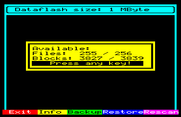
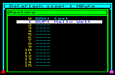
Indicates the assignment status of the file system |
 |
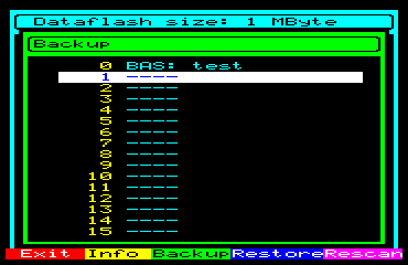
Saves all programs to the Dataflash module |
 |
Loads all programs from the Dataflash module |
 |
Test the dataflash again (eg. after change) |
 |
Deletes a file |
 |
Formats the Dataflash module |
|
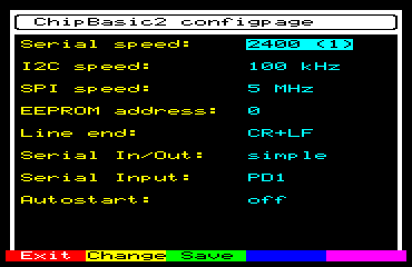
Leave config page without saving the changes |
 |
Change selected setting |
|
Save settings and reboot |
|
Cancel without saving |
 |
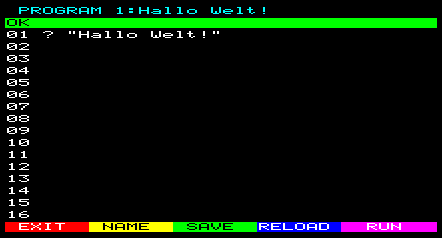
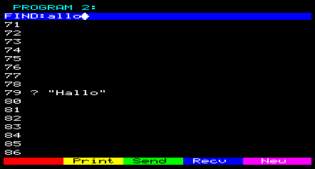
Change the program name |
|
Saves the program in internal flash, in the current slot |
|
Reloads the program in the current slot from the internal flash |
|
Starts the program |
 |
Printout of the listing via the printer (LPT) interface |
|
Transmit of the program via the serial interface |
|
Receive of a program via the serial interface |
 |
Deletes the program (all lines empty) |
| Cursor keys | Move the text cursor within the lines (horizontal) or between the lines (vertical). |
| Page Up | Moves the text cursor up 8 lines or all the way up to the top line 1 if keep pressed. |
| Page Down | Moves the text cursor down 8 lines or all the way down to the bottom line 95 if keep pressed. |
| Home | Sets the cursor to the first character of the current line. |
| CTRL + Home | Sets the cursor to the first character of the first line. |
| End | Sets the cursor to the last character of the current line. |
| CTRL + End | Sets the cursor to the first character of the last line. |
| DEL | Deletes the character under the cursor, characters to the right of the cursor are shifted to the left. |
| Backspace | Deletes characters to the left of the cursor, characters to the right of the cursor are shifted to the left. |
| ENTER | It jumps to the beginning of the next line. |
| TAB | Spaces are inserted so that the cursor moves in the editor by 3 characters. Useful for indents in the program text. |
| ALT + Insert | A line is inserted at the current cursor position. All lines from the cursor position move downwards, the last line in the program (95) is lost! |
| ALT + Delete | The line of the current cursor position is deleted. All lines below the cursor position move up, an empty line is added at the bottom of the program (95). |
| CTRL + C | The current line is copied to the buffer. This is indicated by a BUF=line number in the upper right corner of the screen. |
| CTRL + X | The current line is moved to the buffer and deleted. This is indicated by a BUF=line number in the upper right corner of the screen. |
| CTRL + V | The buffer is copied to the current line. This line will be overwritten. The buffer indicator on the top right disappears. |
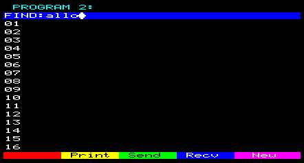
| CTRL + F | Activates the search function, description in the next section. |
|
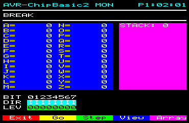
Ends the monitor and triggers a break (exits the program) |
 |
Ends the monitor and resumes program execution |
 |
Execute the next statement and then return to the monitor |
 |
Displays the current output screen, each press of the button returns to the monitor display |
 |
Change to the array display |
|
Ends the monitor and triggers a break (exits the program) |
|
Button is locked |
|
Button is locked |
|
Button is locked |
|
Change to the array display |
|
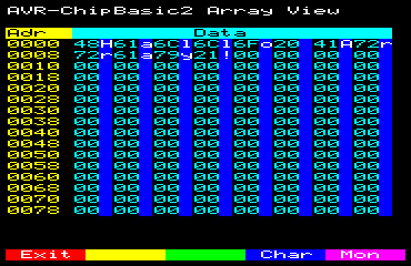
Ends the monitor and triggers a break (exits the program) |
 |
Selects the previous XMEM Page, after 00 follows FF. |
 |
Selects the following XMEM Page, after FF follows 00. |
 |
Toggles the character display on and off |
 |
Returns to the main monitor screen |
 |
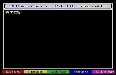
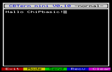
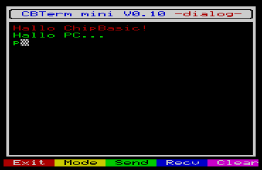
Leave program |
 |
Change the mode (normal / dialog) |
 |
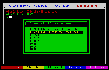
Send a program using the X-Modem protocol |
 |
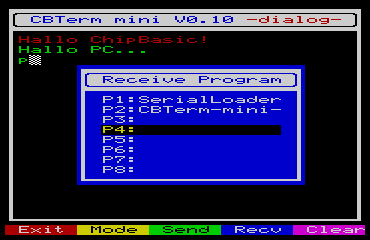
Receive a program via the X-Modem protocol |
| Empty text window | |
| ASCII code | button | action |
| 0x08 | Backspace | Deletes last character, but only until the beginning of the current line |
| 0x0a | ENTER | Linefeed (depending on the "Line end" setting in the configuration page) |
| 0x0c | F4 | deletes the text window |
| remaining <128 | Letters / numbers / signs | Output characters |
| Communication mode | BASIC commands used for transfer | Server sent data format | Notes |
| Graphics | SPUT, SGET | [YXFBCYXFBC...ENTER | [=Start of graphics transmission (91) Y=Yposition (0-21) X=X position (0-29) F=foreground color (0-15) B=background color (0-15) C=transfered character (in HEX or numerical ASCII value) ENTER=Stop of transmission (234) |
| Graphics+Sound | SPUT, SGET | [YXFBCYXFBC...]SS SSS SS...ENTER | [=Start of graphics transmission (91) Y=Yposition (0-21) X=X position (0-29) F=foreground color (0-15) B=background color (0-15) C=transfered character (in HEX or numerical ASCII value) ]=Start of sound transmission (93) S=transferred note (0-255) ENTER=Stop of transmission (234) Pause times between notes are done with WAIT or SYNC commands. |
[ Y X F B C ENTER |
01 SPUT 91,10,15,12,15,$2B,234 |
01 SPUT 91,10,15,12,15,$2B,2,14,2,15,$3A,234 |
SPUT [ Y X F B C ENTER |
SPUT [ |
SPUT [ |
SPUT [ Y X F B C ENTER |
01 SPUT 91,2,10,12,8,$2B,93,50,234 |
01 SPUT 91,2,9,12,8,$2B,2,10,12,8,$2B,93,50,60,234 |
01 SPUT 91,2,9,12,8,$2B,2,10,12,8,$2B,93,50 |